 Virtual Colossus
The rear racks
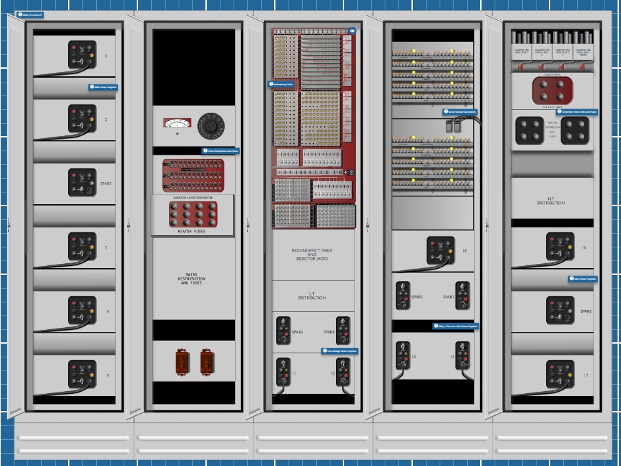
ERNIE’s five rear racks, numbered 1 to 5 from left to right, hold more of the many DC power supplies needed to run its valves and transistor circuits, the fuses and power distribution, the all-important redundancy table, the serial number generator and the teleprinter drive units.
Power supplies
The rear racks hold most of the larger 200 V and 50 V DC power supplies for the valves and the cold-cathode tube counting circuits, as well as the lower-powered −6 V, +8 V and 25 V units used for all the transistor circuitry. Again, with redundancy and reliability in mind, the designers included complete spare units of each type, ready to replace a failed one with just a switch of the cable.
At the bottom of the second rack are the circuit breakers, which can also be tripped with the emergency stop button on the main console, removing all power from ERNIE. One circuit breaker is for the AC mains input and the other for the 80 V DC input from the backup batteries.
ERNIE has its own AC power generators (with, of course, a complete spare running and ready to take over if the first fails), along with a DC battery backup.
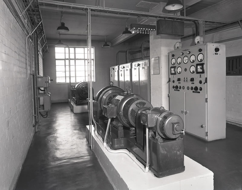
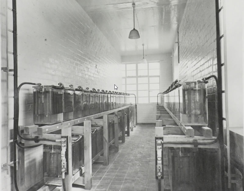
Each DC power supply feeds the main distribution panel on this rack, which has a standard GPO No. 4 detector, with a switch for the operator to choose which of the 18 power supplies to show.
The serial number generator
The serial number generator has five decade counters (although only four were in use when ERNIE was first built). A serial number is printed against each bond number generated, to keep track of the order the numbers were made in, as the higher-value prizes are allocated first.
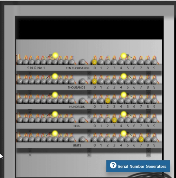
The generator is made of chains of cold-cathode tubes, with a separate counter for each digit (units, tens, hundreds and thousands), which not only lets a pulse step the counter on but also shows its current value.
Each cold-cathode tube needs 100 V to fire, so to start the counter, a 100 V start pulse is applied to the first counting tube, storing the digit 0. This also puts a +50 V bias on the next tube in sequence (1). When the next +50 V counting pulse is applied to all the cold-cathode tubes, it raises the tube with the +50 V bias to the 100 V it needs, so it fires, biasing the next tube along (2) and putting out any other tubes. This carries on until the ninth tube, which biases a passing-on tube that fires on the tenth pulse and steps the next counter on in the same way (the tens, in this case), as well as firing the 0 tube, ready to start again. A set of auxiliary cold-cathode tubes (on the left) turn the steady state of the counters into the pulses the character distributor needs when reading off the serial number digit by digit, starting with the thousands and working down to the units.
Again, as with many other systems, ERNIE has a complete spare serial number generator ready for use.
The redundancy table
The redundancy table lets ERNIE suppress the printing of bond numbers that aren’t valid for the draw, for example a range of bonds not yet sold. This greatly reduces the work for the staff finding the bond photocopies in the filing system, and also shortens the draw by quickly moving on to a more likely valid number.
The first draw, in June 1957, had 48.4 million bond units, but ERNIE could choose from 720 million possible numbers (24 × 30 million). It wasn’t practical to store all 48 million sold numbers in ERNIE, but the redundancy table was able to reject all but 118.1 million numbers in the June 1957 draw, leaving the remaining invalid bonds to be discounted by hand.
The redundancy table uses just the first four characters of the bond number generated: the 10-million digit, the denomination (£1, £2 … £500), the 1-million digit and the 100,000 digit. So ERNIE can only reject numbers in blocks of 100,000 and up. The table’s final output is a simple “number is redundant” pulse, telling the master control to erase the current number from the primary store and generate another. If there is no redundant pulse, the number moves to the secondary stores, ready to print. The table is designed to fail safe: a fault is likely to accept an ineligible number rather than reject a valid one.
The table was set by physically inserting or removing transistors in the right places and strapping connections between sections. This was done once a month, worked out from tables giving the highest number sold in each denomination, plus a small number of groups of numbers missing within those sold.
General layout
The first two sections are each a grid of copper strips, with each row and column made of two strips insulated from each other. Where they cross, a transistor can be fitted, component down, into a hole drilled in the board, with its three wires sticking up (see the diagram below).
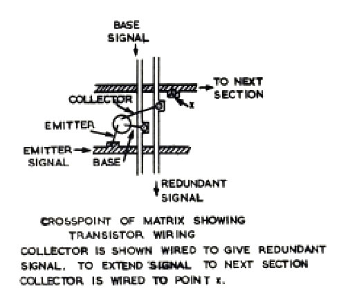
A pulse is fed into one of the strips from the top and one from the left, depending on the digits of the bond number being checked. They meet at a particular crossing point, which is wired each month to give the right output.
If a transistor is fitted, its base is connected to the left-hand of the vertical strips and its emitter to the lower horizontal strip. The collector can then be connected to one of two tags, on either the horizontal or the vertical strip.
The redundancy table deals with two types of redundancy: terminal redundancy, for numbers above the highest bond sold in a denomination, and intermediate redundancy, for unbroken blocks of 100,000 numbers within the range issued.
A button disconnects the table’s output, so every number generated is printed, for testing and for setting up the cyclic tester.
Section 1
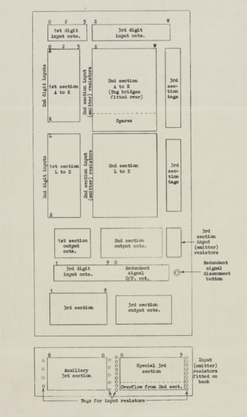
Section 1 is a grid comparing the first two characters of the bond number: the 10-million digit and the denomination code. It is split over two boards (for ease of construction), the two boards at the top left of the redundancy table.
The 10-million digit arrives as a pulse on one of the vertical strips in this section. For the first draw, ERNIE was set to generate numbers up to 30 million only, but space was left to expand to 60 million in future, which is why the board is numbered 0–5 across the top but only 0–2 have transistors fitted.
The denomination pulse arrives on one of the strips from the left (marked with the letters A–Z). The £1 to £10 denominations (A–K) are on the top part of section 1, and £20 to £500 on the bottom part.
For example, suppose the highest-numbered £1 (denomination A) bond sold for this month’s draw is 15,470,976. The first step is to compare the denomination with the first digit, which here could be 0A, 1A or 2A. To set this on section 1, first find the crossing point of column 0 and row A (the first row down). Every bond number under 10,000,000 has been sold, so we want every number from 0 to 9,999,999 in the draw. We do this by leaving the space empty: remember, by default a number is assumed valid and printed. Next, column 1 with the same row A covers the numbers 10,000,000 to 19,999,999. Just over half the bonds in this batch have been sold and the rest haven’t, so we need to pass this further into the redundancy table to check the millions and 100,000 digits. To do this, fit a transistor in the 1A position and wire its collector to the horizontal strip running towards section 2 on the right. Only one transistor on each row should be set to this, so we know which first two characters are being compared when checking section 2 onwards.
For the last block, 20,000,000 to 29,999,999, none of the numbers have been sold yet, so we can set all numbers starting 2A as redundant. Fit a transistor in column 2 (as in column 1), but this time wire its collector to the vertical strip on the right. Any transistor connected to this strip sends a redundant pulse to the master control, which deletes the number from the primary store and starts looking for a new bond number.
There are also two special options. The first is for when more than one 10-million column needs connecting to the second section for a single denomination: there are three extra rows at the bottom of the top part of the second section, which can be wired directly for this. The second is to wire the collector straight down to a special auxiliary section, which can cope with a few “special cases”.
In Virtual ERNIE: to set a transistor, click or touch the crossing point you want to change. Each click cycles through: no transistor, redundant, next section, spare. Or right-click (or long-press) for a menu, where you can choose exactly which mode you want. You can only choose which of the three spare lines to connect to from the menu, and connecting to the special auxiliary table isn’t yet possible in this version.
Section 2
Section 2 is very like section 1, but larger, as its columns cover all ten values of the millions (third) character. The columns are labelled with the letters that appear on the bond (Z = 0, B = 1, F = 2 … W = 9). The grid of copper strips and the way transistors are fitted at the crossings are the same, with a few additions for the many more cases where more than one million group needs extending to the next section. Section 2 is the two larger boards to the right of section 1.
As only one transistor per row can be wired to the horizontal strip that extends to the next section, the GPO added removable bridges that could be fitted across each row of the top part. These bridges have a row of turret tags, so a transistor’s collector can be connected to one and then wired to the third section. The bridges were removed later in ERNIE’s life, when the number of unsold intermediate blocks had dropped.
In Virtual ERNIE: to hide the bridges so you can see and change the transistors, click the eye icon.
In this section we compare the signal from section 1 (where we checked the first two characters, the 10-million digit and the denomination) with the third character, the millions digit. Continuing our section 1 example, with £1 (A) bonds sold up to 15,470,976, the only value extended into this section is 1A, so all the transistors on the A row here are checking 1A against the millions columns. Again, as before, we can leave out a transistor for a million that has been completely sold, connect the collector to the horizontal strip to extend to the next section, or connect it to the redundant strip for a value that should be removed from the draw. We can also connect a transistor to the bridge (shown in Virtual ERNIE as a blue transistor wire) and so on to the third section, or wire it directly to one of the auxiliary or special third-section boards. Our example’s third character is 5 million, so we leave out the transistors for 0–4 (Z, B, F, K and L), as 10–14 million are definitely sold. Then we wire the N column (5 million) transistor to the next-section tag, so ERNIE checks further digits, and wire all the remaining transistors to the redundant strip.
The tags to the right of the second section are wired to the third section, so connections between them can be made with short cross-straps. As the third sections are the last to be checked and don’t extend to another section, they don’t need separate lines for each row. So the third sections are a fixed set of transistors that check particular ranges of 100,000 values, and several rows can be wired to each. Section 3 has 9 possible rows to connect to, so there are nine tags on a board next to section 2, permanently wired to these rows. There are several groups of tags, to make it easier to wire from the nearest section 2 extension strip.
In Virtual ERNIE: click or touch a transistor connection point to cycle through: no transistor, redundant, extend to the third section by the fixed strip, extend to the third section by the bridge (shown with a blue wire), and extend to the auxiliary or special tables. Right-click (or long-press) for a menu where you can choose these more easily; if you choose a bridge or auxiliary/special connection, you get further options for which part of the section to connect to.
Section 3
To understand how the tags between the second and third sections are set up, you first need to understand the layout of the third section itself. As separate denomination lines are no longer needed (nothing passes on to a further section), the transistors in the third section are laid out in a fixed pattern, and one or more section 2 rows can be connected to it. First come nine transistors for making 100,000–900,000 redundant (1–9), then eight for 200,000–900,000, and so on down to a single transistor for 900,000 only. There is no 0, as making the whole set from 0 to 9 redundant can be done with terminal redundancy in the second section. This triangular layout is arranged as a rectangle to save space on the table (see the animation below).
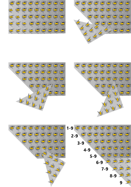
So for our example, 15,470,976, we want to make everything from 500,000 upwards redundant. We connect the A denomination’s extension from section 2 to the section 3 row for 5–9, so any fourth digit of 5 or more gets a redundant signal and is deleted. To do this on ERNIE, the tag at the end of the A denomination strip on section 2 was wired to the 5 tag in the group of tags leading to the third section.
In Virtual ERNIE: to change the wiring from section 2 to the section 3 tags, click the end of the wire you want to change, just where it reaches the section 3 tag board. Each click moves it to the next tag along, in turn. For example, to change the A denomination, click the wire at the top left of the third tag section, just to the left of the number 1.
This deals with redundant numbers at the top of a block of 100,000, but if there are unsold bonds at the start of a block of 100,000, we need to connect to the auxiliary section 3. This table sits just below the standard section 3 table and has the same layout, but is wired to make anything from just 0 redundant (0–99,999) up to everything from 0 to 8 (0–899,999). Connecting to it means strapping by hand from the collector of the relevant section 2 transistor.
In Virtual ERNIE: right-click a transistor and choose Fit Transistor → Aux/Special, then right-click again and use the “To 3rd section Aux” list to choose which part of the auxiliary table to connect to.